In this video tutorial, I offer up a brief modeling tutorial on how to use the engineering draft feature inside PTC Creo Parametric modeling software.
Last time I touched on the fundamentals of draft angle, especially when designing objects that will be mass-produced using injection molding, casting, or other forming processes. Our illustrious subject will be the good ‘ole no frills trash can. They come in all shapes, sizes and materials. The one thing they all have in common: draft.
When it comes to 3D modeling packages, Creo Parametric contains a suite of tools that are wide and deep. The Draft Feature within itself has the flexibility to achieve basic draft such as in our tutorial today or complex, curve-driven split draft.
Only three inputs are needed to successfully create a draft feature: 1) Draft Surfaces, 2) Draft Hinges, and 3) Pull Direction. Pick’em right and you’re in business.
So, without further ado, feel free to dive into the video.
In summary, the steps to create draft using the Creo Parametric basic draft are depicted in this final image.
I believe there’s a study somewhere that shows 78% of Engineers and Designers, who plan a move into a management position, plan to light their office with industrial-chic light fixtures using vintage light bulbs… That figure may have been 7%… Numbers, Meh. Anywho, vintage light bulbs are all the rage, and judging by the 2000+ downloads of #David’s Vintage Bulb Set, a few people like the 3D models as well.
#David needed some bulbs to light some fixtures he was designing. He decided on some Bulbrite Nostalgic Edison lights, bought them online and went to work modeling up the incredibly stylish bulbs in SolidWorks. He has included three bulbs: The Bulbrite T14 Vintage Spiral Filament, the Victor Loop A19, and the Clear Dimmable ST18. Great choices #David!
The SolidWorks file contains three configuration plus one with the E26 (Medium) base only, in case you want to add another style to the mix. He has also included a STEP file with all bulbs and base for those who don’t have SolidWorks. Ima light this mother up! I have now idea what that means, but it seems the right time to say it. No? Oh, ok.
You can download the files on GrabCAD. (BONUS! Grab this sweet light fixture by Jack Townsend that looks GREAT with the bulb Download here!)
I’m pretty sure LEGO minifigs have all the fun… except for, ya know, being completely inanimate and having the dexterity of a cardboard box. Besides that, they get to play around on and endless number of cool cars, aircraft and THIS, this LEGO Technic Dune Buggy.
Some of you may know this vehicle as the 8048-1 Buggy set, released in 2010, containing 314 pieces and cool, little ‘Nitro Buggy’ decals. If you’re GrabCAD user ‘lowradiation’ however, you know every single piece intimately, from the four-knob gears to the shock absorbers. He has a long history of making these LEGO sets, with over 20 available, many of which are in the Technic category.
For this model, he’s provided the model in both STP and (Rhino) 3DM, perfect for downloading, rendering, animating or using to complete more of your digital LEGO collections… because a digital LEGO collection is really useful and doesn’t hurt as bad when you step on it. Does a LEGO feel pain when it steps on itself? – Existential quandary for LEGO minifigs.
Well, well, well. Just as you were getting comfy with the limited private storage of Onshape’s free plan and dumping your Documents occasionally to clear room for others, they’ve gone and switched things up on you.
As of this week, Onshape is offering a new 21-day Pro plan trial with no storage limits, unlimited private Documents and full CAD-crafting features. The Pro plan price stays the same at $100/month billed annually, but changes to $125 for those who want the convenience of paying more monthly. If you don’t continue on the Pro plan, you’ll be put on the Free plan (and given a sad face sticker), retaining unlimited public Documents and the same CAD functionality, but minus Private document storage, sharing and collaboration.
Windows, Mac, Linux, Chromebook & Mobile (iOS & Android)
Windows, Mac, Linux, Chromebook & Mobile (iOS & Android)
Windows, Mac, Linux, Chromebook & Mobile (iOS & Android)
Common CAD Format Import/Export
Common CAD Format Import/Export
Common CAD Format Import/Export
Centralized Billing
Centralized Billing
Company Document Ownership
Company Document Ownership
Administration Tools & Controls
Reporting & Analytics
Enterprise Support
If you’re currently on the Free plan, and have private Documents, you have until December 15th to switch to Pro. If you don’t, and your Documents are not made public, you’ll be able to access them, but not edit them–they’ll just be sitting there, looking at you, giggling indistinctly. So, time to export your models, publicize them or bite the $100 bullet and upgrade to Pro. If you’re already a Pro customer and paying monthly, there will be no increase in price and you can keep it for any new users you add.
Along with these changes, Onshape is adding more features to the $200+ Enterprise edition to sweeten the deal for large design teams. Some of the features they’ve already revealed are reporting and analytics, and admin tool and controls.
Like the new features? I’ve always said, sell the features, not the storage. There will now be more people creating more public models, which is more sharing among the Onshape community and more knowledge being shared, less pressure to move to Pro, but an easy decision if you need the private features. Good move Onshape, good move.
CLO is to soft goods what SolidWorks is to machine parts. Game, consider yourself changed.
How we can illustrate this? Hmm. Ah yes…
Form-fitting Spandex Activewear. For Dogs.
You awake with clammy forehead skin, itchy fingers, and the germ of an idea that will change the world. You roll out of bed, gorilla walk across the snack food strewn floor, and wince as the piercing cold blue of ultra-bright OLED shatters the warm, musky darkness. SolidWorks.
You heave a sigh of relief as you enter your Parametric Happy Place, crack the knuckles of your sausage-like fingers, and, quietly, contemplatively, you hear yourself mutter: Maximum effort. It’s design time.
You stare blankly at the screen.
Have you ever tried to design spandex dog garments in SolidWorks? Words like “hopeless”, “asinine”, and “meat-headed” come to mind.*
* If you have actually attempted to design spandex dog garments in SolidWorks and are offended by any of the above word choices, get over it.
There have traditionally been two overarching phyla in the 3D design kingdom: Digital Content Creation (DCC) tools, and Computer Aided Design (CAD) tools. DCC’s are designed for makin’ pretty pictures for print, games, and movies. CAD is for designing hard-body objects in the real world. CAD is for designing objects in wood, metal, plastic, ceramic, glass: buildings (AEC), mechanical engineering (MCAD), and exterior shape design (Surfacing).
There is no existing category of 3D tools for the design of soft goods. Products made of wool, cotton, nylon, and Spandex are still, to this day, largely designed the old way. Designers pass 2D illustrations to skilled pattern makers, who, in turn, hand-make round after round of successive prototypes. Once a prototype is approved, its pattern can be drawn in a 2D vector drawing tool like Adobe Illustrator, then used to drive 2.5D CNC cutting machines for production. It’s slow, arduous, and, most importantly, requires a lot of guesswork, trial, and error.
Intrepid studios have long experimented with various 3D tools for soft goods design. DCC apps are favored by those who like the freedom that non-reality offers, but are then hindered by the lack of dimensional control or useful pattern output. CAD apps are typically favored by studios working with crossover products like shoes, luggage, or wearables. These products already contain elements of hard-goods design for which CAD is the perfect tool: rubber soles, wheels, plastic frames, and metal fixtures. CAD falls down, however, when asked to design the kinds of complex organic forms that Spandex demands.
CLO (big-sister to Marvelous Designer) is not a DCC, nor is it CAD. It represents an entirely new phylum. It allows users a level of fluidity, speed, and flexibility on par with that of a Visual Effects (VFX) design tool like Z-Brush, the ease-of-use on par with quasi-CAD poly modeller Sketchup, and the downstream manufacturing efficiency of a CAD tool.
With CLO, you can design soft goods around an existing 3D model, not unlike a cobbler’s last. Design patterns using simple 2D vector drawing tools, position them in 3D space, sew them together, and simulate the fall of the fabric across the last.
Most of the demos you’ll see are based around human mannequins, but you could just as easily import a dog, an iguana, or the latest MCAD data from that 9-axis robotic arm you’ve been designing. When the visual result in CLO looks good, you can export your pattern curves for the CNC cutter, and off you go.
As wearables come into vogue, we’ll need more and more tools like CLO to fill the role that CAD plays in the hard-goods world. I hope to see more of them. For now, try out Marvelous Designer. It’s free to try, and CLO really just adds pattern export features.
Do you use either? What for? And bonus if you’re using it in a workflow along with an MCAD tool like SolidWorks.
If you want to find out what Autodesk is up too, Autodesk University is the place to be each year. Last week that happened… yep, I just checked and we were in fact at AU last week. It was a bit of a blur, but I know two things for certain, nay THREE — Titos is the best vodka, beatboxing should kick off more conference keynotes, and Autodesk shot out five feature previews for Fusion 360. They’re features many have been gnawing the last bit of their fingernail beds in anticipation of. Some are surprises, some are expectations and others just change the game completely.
In our last article, we looked at what Autodesk had done with Fusion 360, but it’s at Autodesk University–during the keynotes, special sessions and the bartop conversations in particular–where you not only see what’s coming to Fusion 360, but what people are doing with Fusion 360. As you know we loooove the latter, and it’s those people who influence the direction and development of features in Fusion 360. What are those features? Let’s have a look.
This comes from Autodesk’s acquisition of CadSoft with their massive ELEMENT14 userbase and the EAGLE Schematic/PCB Design software. The software will be fully integrated with bi-directional associativity between MCAD and ECAD environments.
Hello. I’ll just let half of you pass out right now… and the other half when you hear it’s ‘Coming Soon’ to Fusion 360. For good reason though–with stiff competition, they’ve been perfecting this to be the best sheet metal available. It looks amazing, from flange creation, miters, feature creation and flat patterns of course, PLUS automatic nesting.
Ever since Autodesk revealed the results of the NEi Software acquisition with Autodesk Nastran, it has been suspected the capabilities would make their way into Fusion 360. The wait is over. Fusion 360 has a new solver, new Contact Manager, Buckling, Bolt Connection, multiple load cases, nonlinear studies, shape optimization and super improved mesh refinement. Lattice optimization also coming to Fusion 360 for light weighting. Bit of a large update.
The CAM capabilities in Fusion 360 were already great, but this is next level right here. Included now are both additive and subtractive capabilities that cover the gamut of machining needs in product development. Along with this are new fixture types, new tools, WSC Probe for stock positioning, 4-axis index and wrapping, and 5-axis swarf machining.
Fusion 360 is coming to the browser. Though not specifically mentioned, this is an outworking of Project Leopard (still in beta). No date has been set, but the intention is clear–the ability to use and access Fusion 360 anywhere on any device. Though the current desktop download/installation has been a criticism, it’s a move driven by customer need and cloud capability. Now, both are there with Fusion 360 Browser Access ‘Available Soon’. Note: the shot we got at AU above shows CAM. However, CAM won’t be supported initially, but toolpaths, simulations, and other related data will update in the browser view when geometry is changed.
BUT WAIT…
If you were not watching (I wasn’t), you may have missed (I did) the announcement that Fusion 360 Ultimate IS BACK.
They originally announced Fusion 360 Ultimate in October of 2014, adding features that didn’t exist in Fusion 360 at the time, including 3-axis CAM. Then they took all of those features and bundled them into the lower price of Fusion 360 Standard for $40/mth ($300/yr). Now, they’re playing with our emotions and bringing Fusion 360 Ultimate back, adding advanced (buckling, nonlinear) simulation and advanced (Probing, 4/5-axis) machining for $190/mth ($1500/yr).
So, Ultimate is back, and Autodesk has revealed features, many that you’ve been waiting for and some requested since Fusion 360 was first announced. Personally, I can’t wait for sheet metal, and I’m wondering what’s going to be the most useful for you, but most of all, I’m wondering how you’re using it–do let me know in the comments. And if you haven’t tried it yet, snag Fusion 360 here.
Think about it. What are you suppose to do with your fingers when you’re not CAD’ing about or peeling through the pages on SolidSmack? You could eat… or make stuff… or give your co-worker a very awkward massage, OR you could fidget. Fidget, fidGET, FIDGET. I’m a pen spinner myself, but Francesco Pantaleone has just revealed to me another way to fidget my life away.
Francesco says, “This Trispinner is smaller than other designs on Thingiverse” ….wait, there are more?! Sure enough. There are no less than a thousand other fidget spinners on Thingiverse, but this one, THIS ONE, is designed so it spins between the fingers at every position. “LET THE FIDGET TRICKS MADNESS BEGIN!!”
It’s a beautifully simple design printed with ColorFabb Woodfill at 0.20 mm layer height on a Prusa i3 MK2. I am absolutely impressed with the results on that printer – look how tight those layers are! Though not specified, it looks like it uses standard 608 ZZ bearings (22mm OD x 8mm ID x 7mm Width).
This post features affiliate links which helps support SolidSmack through a small commission earned from the sale! Thank you for your help in moving away from banner ads by delivering better content!
Mathieu Stern is a photographer, and also a collector of old, cheap and weird camera lenses. So, it makes sense that he would set out to create his own 3D printed camera lens, and you know what? “What?” Well, it takes a dang good photo. Check THESE out.
Mathieu says, “I never really learned how to make 3D models on a computer–I started by making a cardboard first prototype with a found lens from 1890 I had in a box. It was ugly and not easy to use but I was able to focus and take the measurements I needed to create a 2D design.”
He got rejected by a lot of 3D printers (because of the cost of creating it and the lack of funds to make it happen), but he finally found a printer willing to take a chance. FABULOUS, a 3D printer in France, took his idea and turned it into a photo shooting prize to behold.
“I met Arnault Coulet, CEO of a French 3D printing agency called FABULOUS. His team and he designed the 3D prototype and printed the lens. Luckily for us, he saw all the crazy potential and fun we could create with this project.”
The lens is simple, a 135mm f/1.8 lens that was made up of two cylinders threaded together. The first cylinder, containing the glass lens (the nineteenth century one he found in a box), moves back and forth to allow focusing. The smaller, inner cylinder attaches to the camera. This section contains a slot for a diaphragm plates with various shapes which add visual effects to the image. The created the 3D model (in Rhino?) and 3d printed it using PLA on a Leapfrog 3D printer.
In the end, it was proof a camera lens could be printed and printed at a cost of only “a few Euro.” You can download the files via Sketchfab!
Right when you think everyone gave up on putting parametric 3D CAD software on an iPad, a small, rebellious group of software developers launches an app that puts those large, money-laden software companies to shame. When we first saw Shapr3D, it was well on its way to cracking the CAD app conundrum – How do you put functional parametric 3D modeling on an iPad? Well, they’ve doneit, and just released Shapr3D 2.0 that brings a few things it was missing.
With powerful laptops and 2-in-1s flooding the market, why put CAD on iOS now? I thought as much, giving up on ever seeing ‘SolidWorks for iPad’, but with the big CAD companies losing interest in the same and the iPad Pro + Pencil just out, it was a perfect time for others to pick of the task, and Istvan Csanady, founder of Shapr3D, believes their app to be a huge step forward in the life of the first truly mobile CAD software.
Six month ago, they launched the first version of the app with basic sketching, solid modeling and freeform surfacing features. To their surprise, it was hugely popular. They received loads of praise, even more feedback and many suggestions for improvements. “We thought people would just use it as a 3D sketching app,” Istvan says. “We were totally blown away when people started showing how they used it across different industries: architecture, jewelry design, engineering, industrial design, interior design and more.”
Constraints and Dimensions
In Shapr3D 2.0, they’ve refined the workflow and Apple Pencil interface, but the main focus has been on sketching and constraints. If you us any constraint-based CAD software, it’s going to look extremely familiar. Using your Apple Pencil, you can sketch lines, arcs, circles and splines (without pressing a single button or using ridiculous key combos). It work just like you would expect. Have a look.
The constraints even work with splines.
Education
The Shapr3D team is serious about getting their app into the hands of new users, announcing that Shapr3D will be free for students, professors, and educational institutions. “Shapr3D is a great tool to learn 3D modeling. This is why we decided to launch our educational program: all the pro features of Shapr3D will be free for educational purposes, without any limitations.”
Along with all of this, they’ve redesigned how layers and groups work and have improved the extrusion method by allowing a sketch, shape or face to be pulled directly. New in-app tutorial videos have also been added. Native CAD formats have not been added, but you can export as .STEP and .IGES and .STL.
Shapr3D 2.0 is currently available on the iTunes App Store as a free download with in-app subscription purchase options: Shapr3D ($19/month), Shapr3D PRO ($99/year) and Shapr3D EDU (Free). An Apple Pencil is required for using all Shapr3D features.
When I bought a 1st-gen iPad in 2010, my first thoughts turned to the possibilities of using 3D CAD on the super mobile, touch-screen device. Waaaaay back then, I was still using a massive desktop for major CAD tasks. I have a smaller computer now, and a small mobile laptop capable of running any 3D CAD software, but I’ve already planned to purchase an iPad Pro and Shapr3D is the first app I will install.
Have you used Shapr3D 2.0? What features do they need to add next?
Was bound to happen sooner or later, right? We started worrying about this all the way back in 2011 when Autodesk acquired T-Splines. The small Utah-based company had a growing Rhino user base for its plugin that provide a unique take on organic modeling in a solid modeling environment, and they had just released a similar plugin for SolidWorks. The tsElements plugin was discontinued and now T-Splines for Rhino is headed to the burial plot, which completely ends T-Splines as it has been known.
As Tom Finnigan, Software Architect at Autodesk, announced on the T-Splines blog, this affects more than just the T-Splines plugin for Rhino:
“Autodesk will no longer develop new versions or sell the T-Splines, Shape Modeling, and Real-time Renderer Plug-ins for Rhino. We have made this decision to simplify our portfolio and focus efforts to better serve our customers with Autodesk products.”
In the FAQ issued, Autodesk explains that they “will not update these plug-ins for Rhino V6 or any future versions” because they have “developed products that include these underlying technologies and provide similar capabilities.”
The last announcement, for T-Splines V4, was in January 2015 from former T-Splines Founder and CEO, Matt Sederberg, who went on to become Automotive Design Product Manager at Autodesk, and has now moved on to start another company called Isogeometrx, a company that is “dedicated to revolutionizing design and engineering in the automotive, marine, and aerospace industries by providing tools and technologies for integrated design and analysis.”
In Febraury 2014, Autodesk discontinued tsElements (T-Splines for SolidWorks) with the reason that “a community never really had a chance to coalesce around the concept before T-splines were acquired by Autodesk.”
tsElements for SolidWorks added organic modeling inside SolidWorks.
We knew the end would eventually come to T-Splines support for competing products as it was absorbed into Autodesk products (currently Fusion 360 and Alias). That tsElements lasted three years and the Rhino plugin lasting six shows that Autodesk was at least slightly dedicated in keeping the products going. At least long enough to ask them, “Have you tried Fusion 360?”
The T-Splines 4.0 download for Rhino 5 is still available here. The tsElements plugin for SolidWorks is no longer available for purchase, but is reported to work in SolidWorks 2016. Those with T-Splines 3.5 or later will be able to activate their licenses on new machines indefinitely.
So, there are at least two questions. Will Rhino get a new SubD plugin? And, what are you using instead of Rhino + T-Splines?
Not sure if you realize this, but Onshape broke out of beta exactly one year ago. They celebrated their first birthday this week with a tiny chocolate cake I’m sure was fought over after this photo was taken. Not sure why Kevin Bacon photo-bombed that lovely picture. Rude.
It honestly feels longer, doesn’t it? Especially with the rate of updates they were churning out – I count 5 or 500… not sure, somewhere in between there. An update every few weeks. Jon Hirschtick: “15 updates, 120 new features/enhancements.” Well there you go. They must have a few goals. They definitely have a growing user base, as we hear from professionals all over that they’re trying Onshape or using Onshape with others asking, “Have you heard of Onshape?” – yes, we get that question, more than you would think.
Given that we’ll take any excuse to eat cake whether we’ve been offered it or not, we thought it was time to crash the party and catch up with Co-founder and CEO of Onshape, Jon Hirschtick, to find out what the last year has been like, what they’ve learned and what their goals are for the future. Let the cake eating commence!
SolidSmack: Can you break down some Onshape stats for us?
Jon Hirschtick: Over 2,000,000 hours of usage! And 1 in 6 Onshape sessions are from a phone or tablet (Android, iPhone, or iPad).
Any interesting internal stats with that?
We have 3 refrigerators
We have 2 coffee machines — one Keurig and one that grinds the beans
We are in Sprint 57 — meaning our 57th ‘period’ of R&D
I have sat at 3 different desks in our office
How many times users have installed Onshape: Zero
How many people have downloaded Onshape: Zero
Speed of my home internet connection: 330Mbps (ok, it cost me an extra $7 per month). Approximately 5 times faster than when we started Onshape. Score one for full-cloud apps.
Speed of the newest CPUs compared to the old CPUs that were around when we founded Onshape: The same. No improvement. Got it?
It’s clear Onshape has shaken up the CAD scene. What did you expect would happen? What didn’t you expect would happen that did?
I expected that we would assemble a great team of people — and we did.
I did not expect just how much interest there would be in a true cloud system.
I did not expect to see so much interest in, and really a brewing movement among customers to, “Agile Design” — basically a change in their process to be more iterative, nimble, involve more people, and move faster. Customers want to change their process, and they see that traditional file-based installed CAD is not well-suited for Agile Design, but Onshape and our full-cloud database architecture are great for Agile.
We also did not expect just how fast/powerful tablets and phones would get (like the iPad Pro I am writing this email on — we knew we were going to run on them for sure, but I did not quite expect how much performance has improved on mobile the past few years.
I’m also surprised that nobody else has yet come out with a true, full-cloud system like ours. Someday I expect they will, but so far we still are alone with our full-cloud approach.
AGILE DESIGN – FEMC, a leading food packaging machine company for global brands, credits the Agile Design properties of Onshape for dramatically reducing its design and manufacturing cycle from three months to three weeks. Pictured here is a concept design for a new gravy-filling machine for a frozen food product.
Along the same lines, what’s been the most surprising development in Onshape to you over the last year?
The most surprising development in Onshape has been to see 40 different partners build apps using out API. It’s also been very surprising to see how reliable our full-cloud architecture is. Sure we have bugs and issues like any CAD system, but the notion of ‘crashes’ that plague installed CAD has been enormously reduced. Very surprising and cool to those of us who have built CAD systems for years.
Has the speed and which people/companies are transitioning to the cloud shifted? If so, has it changed how Onshape is approaching things?
Yes, more companies are accepting and embracing cloud, and faster than ever. One customer used to tell me a few years ago that they could not use cloud solutions. Now the same customer told me that he has a mandate from his management to get rid of all of his in-house compute servers, that the company has mandated that they *must* use cloud services.
It’s pretty dramatic actually to see the decline in cloud naysayers and the dramatic increase in cloud enthusiasts. Also, while there are of course still people with bad internet, the number of people with awesome internet is exploding. As I said above my home internet is 330Mbps. I’ve visited schools with 1Gbps.
You’re famous for your ‘Future of CAD’ outlook. Have you had some new thoughts about the future of CAD? If so, what has changed your thoughts?
One thing that hasgrown in prominence in my thinking about the future of CAD is the importance of mesh/facet-based 3D models. They have become much more important to the future of CAD than I might have thought a few years ago. I think the future of CAD will include great capabilities for importing facet/mesh-based 3D models and working with them as ‘first-class’ objects. Measuring to them, referencing them in building parts and assemblies, using them as components in assemblies, performing modeling operations on them (both parametric and direct editing), and even mixing them in a model with traditional Boundary Representation type 3D models.
The reason for this is because of additive manufacturing, generative shape optimization technology, and the enormous advances in 3D scanning. All of this has increased the ‘currency’, if you will, of facet/mesh data, like STL files.
Also, the future of CAD is going to be a lot more about how many, many people can work together in teams rather than what one person can do with merely creating a model. Products are not built by one person, nor can they even be built by an old-style, one-person-at-a-time workflow.
Teams of the future want their CAD to work in real-time: real-time deployment to anyone anywhere on all their devices, real-time data management, real-time collaboration, real-time analytics, real-time controls. There’s no time for the old ways anymore.
REAL-TIME DATA MANAGEMENT – To design a new mobile grain silo, Walkabout Mother Bins CEO Dave Hedt relied on Onshape to enable design team members in the U.S. and Australia to collaborate on the same CAD model in real-time.
What are some goals you want to see Onshape hit over the next year?
The most satisfying and important thing we do at Onshape is to see our customers build real products in Onshape, and do it faster and with more innovation than they ever did before (and have more fun doing it).
So the main goal is to continue, as we have in year 1, to quickly grow the number of customers who are doing this. That’s the biggest goal.
We want to have another huge year of product growth, and improvement too, of course — in all areas: modeling, drawings, speed, applications, collaboration, data management, etc. And we are really looking forward to introducing our Enterprise product with a whole bunch of brand-new features, which have never been part of CAD before, for managing and analyzing and controlling teams of CAD users.
A big thanks to Jon for the interview, for some new thoughts on the future of CAD and the insight into how people are using Onshape. A happy birthday to the entire team as well. As always, we’re interested to see what Onshape is bringing to product development and we’re looking forward to what they do next year!
Take that last swig of cold coffee and check this out. Vectary, the online 3D modeling platform, is now out of beta. We took an early look at Vectary in September. Right after that, in October, they surprised us announcing a Seed round of $2.5 million, led by BlueYard Capital (here’s why), and a move of their HQ to Brooklyn, New York. To catch you up on the platform.
Vectary aims to combine mesh modeling, subdivision modeling and parametric design–all apparent from the interface layout and initial features and toolset. The Vectary UI is a beautiful, wide open environment with your modeling Tools to the left, your model Objects to the right, Snap and View setting at the bottom and Selection options up top.
Founder and CEO, Michael Koor, started as an industrial designer, eventually turning to develop his own software for faster design iteration. He and Pavol Sovis brought that to the web, growing a team focused on the same and developing it into what it is today with the goal of building a community for other designers to have the same access to creating and iterating 3D models quickly.
New and updated features alongside the public release of Vectary include:
New parametric plugins (Mirroring, Array and Revolve)
New array feature in Vectary for creating quick patterns.
The ‘parametric plugins’ sparks our interest the most. These are features under development that include some of the basic tools that are a must in any modeling tool and absolutely needed to make this app even better. Currently, they’re added as layers in your object tree on the right. Along with features like Revolve, Mirror, and Array (Pattern) there are also features for Wheels, Boolean Operations, 3D Printer Export and an interesting ‘Joints and Wires’ feature that will map what look like pipes and fittings along the segments of the geometry you’ve created in your scene.
Library of new features under development in Vectary.
During the closed beta, only the first 10,000 beta testers had access, but now with the VECTARY platform open, beta testers can share their public models online. You can see the most popular models here. If you didn’t get on during the beta, now’s your chance to try it out. Very interested to know what you think.
Some needed features we’re thinking of off the top of our head are:
Who needs a rocket engine? WHO DOESN’T?! And a 3D model of a rocket engine? Well, just think of the possibilities… You could place it randomly in the model of your new product and have a good laugh when everyone starts questioning it during a design review. You could 3D print it, set it on your desk and charge people to touch it. And YES, you could Photoshop your face and use it to give yourself JET ENGINE JOWLS.
Hans de Ridder created this model using SolidWorks, and although it’s mostly modeled up as a single part, it fun to play around with and get some ideas on modeling your own rocket engines or Sci-Fi 3D modely bits to use in a multitude of ways. From the looks of the 60+ pages of his other models he knows what he’s doing too, with all matter of ships, rockets, robots and vehicles.
The SolidWorks .sldasm and .sldprt files are available to download, but you may need to request a .step or .iges version if you use another 3D modeling software. You can download the files via GrabCAD! (Bonus! Check out all the sci-fi ships Hans has created on his project page!)
On the ankle-veins of Autodesk announcing they are shuttering T-Splines, they’ve also announced that they’re bringing the family of 123D Apps to the end. Here’s what we know.
The 123D apps are being consolidated into other Autodesk products and 123Dapp.com is being shutdown. Outside of specifying “early 2017” and “access and download your content from 123Dapp.com in the coming months”, there’s no definite date for when the apps, site or your data will disappear forever.
We are making some changes to simplify our Autodesk portfolio and workflows for people everywhere who love to make things. We are consolidating these tools and features into key apps such as Tinkercad, Fusion 360, and ReMake.
Today, we are sharing the news that in early 2017, after we complete this consolidation, we’ll be shutting down 123Dapp.com and turning off many of the apps to new download.
It’s not too clear what is happening with each of the 123D Apps, but there’s hope that many of them will be added to Fusion 360, especially with Fusion 360 coming to the browser next year.
Regarding 123D Make, Scott Moyse says, “it should be in Fusion 360 for sure! It will be a missed opportunity if it isn’t put into Fusion… it should be in Inventor as well!”
Regarding Circuits, Yuriy Sklyar with Autodesk says, “It’ll still be alive and will eventually be a part of Tinkercad”, and regarding 123D Catch, that it will belong to ReMake, and regarding 123D Make, that “It’s going into Fusion.”
Alternative to Autodesk 123D
While we have a general idea about where the features and capabilities will end up, it may very well be worth becoming more familiar with where they may end up. Here are the three apps to look into:
Tinkercad – A free, (Chrome) browser-based 3D design and modeling tool. Currently in beta.
Fusion 360 – All-in-one platform for solid and free-form modeling, analysis and more – Free for startups, hobbyists, enthusiasts and educators. $300/yr Standard, $1500/yr Professional.
ReMake – formerly known as Autodesk Memento, this is an end-to-end solution for converting reality captured with photos or scans into high-definition 3D meshes. – Free for students and educators. $30/mth or $300/yr.
Remember when life was nothing but eating large amounts of pasta and disassembling engines? Yeah, that was the best! Especially the time you shot noodles out your nose and into the crankcase – that squirrel didn’t even know what was coming. Ah, simpler times perhaps. Though some would question their ability to launch noodles from a nostril, there are plenty who could tear down and reassemble an engine. But what about 3D PRINTING THE ENGINE FIRST?
Yes, never mind the challenge of building an engine – let’s build a working one from layers of plastic that warp if you look at them wrong. Well, Eric Harrell from Santa Cruz is up for the challenge–and it’s not his first time either. His latest project is the model, print and assembly of a fully-functional Chevy Camaro LS3 V8 Engine. The build took over 200 hours of printing (72 for the engine block alone) and, though smaller, the final product assembles exactly like the real engine. Have a look:
Eric modeled the engine in SolidWorks and used a RepRap Prusa i3 to create the scale model that includes 64 unique parts. He has provided all of the .stl files (he’s not releasing the SolidWorks files yet), plus seven files that include assembly and placement instructions. He has also included a hardware list and a complete parts list that includes print and finishing instructions. If you’re ready to start assembling however, he has hardware kits available for $52, and all electronics, which includes the 500 rpm motor, speed controller and power supply, for $27.
He modeled the Chevy V8 from specs, pics, CAD files, and service diagrams of the engine. Three have already built the model and judging by Eric’s other builds, he knows his stuff. He has four other built-to-scale functioning, 3D printed engine builds along with various other detailed automotive projects. My favorite part is the engine stand. Though he doesn’t have parts and build instructions for that yet, he’s gathering supplier and part list to provide that as well. You can email him to be notified when it’s available.
Hop over to Thinngiverse to download the files! (Bonus! Check out Eric’s Subaru WRX EJ20 Boxer Engine here!)
I don’t know when you last played Super Mario Bros. 3 for 87 hours straight… what’s that? Last week? Well, after that you probably had that nightmare where you’re running through Mushroom Kingdom being repeatedly pummeled by massive concrete THWOMP blocks, right? No? Ok, just me. Still, those were one of my favorite obstacles and if you liked them too, then you’ll LOVE this week’s model.
Wes Swain has created a super-size, little THWOMP game console to house a Raspberry Pi (although I’m thinking that sizing it up a little to house the innards of a Super NES with a spot in the mouth to shove the cartridge would be AWESOME.) Why did he do it?
The notion of permanently sealing a functioning computer in a chunk of cement is compelling to me for some reason. This flies in the face of the modern notion of upgradability, patches, updates, & the unspoken reverence for a computer (even this cheap one) and I love that about this project.
WHAT A REBEL. We love that about you Wes.
Not only does this kick practicality in the face, it’s a project that incorporates electronics, 3D modeling, 3D printing, mold-making, and playing awesome, old school video games until someone gets really irritated with you. He has laid out all the step as an Instructable where he takes you through the modeling using Fusion 360, the printing using a LulzBot TAZ 5 and casting using Smooth-on mold-making products.
One thing to note. This is a single part mold with the Raspberry Pi EMBEDDED inside the THWOMP. You won’t be getting this out again… unless you turn invincible or have a Hammer Suit. SUPER MAAAAAARIO!! So, make sure you have everything loaded and connected up right. To protect it, he suggests using a few coats of liquid electrical tape. I’m thinking a two-part mold here and a cavity for the Raspberry Pi – I’m just not as rebellious as Wes is I guess
Have a look at how it came together in the video below, then double-jump over to Instructables for the walkthrough and Thingiverse to download the model!
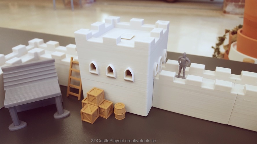
You know when you’re comfy as a lark in your castle and all of a sudden AN ARMY OF THE UNDEAD ATTACK. I agree, kids in this generation just don’t know how to defend against an occurrence of that sort. Your not gonna text your way out of that one! Oh, yeah, get a selfie of that demusclized skeleton warrior as he cuts your face. Fortunately, there’s a modular castle playset that allows you to set up specific castle attack/defense scenarios AND have fun doing it.
The 3D printable Modular Castle Playset is large set of model files, designed by Tim Wahlström in cooperation with the fine team at CreativeTools.se, created for parents and children who want to become more familiar with 3D printing at home. With a castle model that is modular and many more accessories, there is a huge number of castle constructing possibilities and play.
The set contains walls, towers, houses, characters, animals, and a myriad of different props. All parts are small enough to be 3D-printed in a build volume of 140 x 140 x140 mm (5″ x 5″ x 5″). The walls and towers fit together easily using a simple 3D-printable butterfly joint. You can make as many parts as you want to create your original castle layout!
They have release a LOAD of files, 84 in total (and they’re taking suggestions for others). You have the aforementioned items, along with canons, ladders, barrels and boxes. All the .stl files are provided and available on just about any 3D printing related website imaginable. PLA filament is recommends, along with a printer capable of using PLA – a Lulzbot, Ultimaker, Sigma, Prusa i3 MK2 or Rostock Max Delta printer are all good choices.
The only thing their missing is the Settlers of Catan version. Oooo!
Throughout all the years (decades? yeow!) I’ve use 3D modeling software, I can’t think of a time where I didn’t use some type of in-context assembly design. Not building out a design like that gives me the shakes – I honestly can’t grasp how to get accurate fit and function without it. “That there is what them there hammers is fer!” EXACTLY. You just go ahead a beat that fuel line into submission. I’ll stand waaaaaaay over here.
But there are valid reasons why people don’t want to use in-context design in traditional CAD software. Some companies actually ban it or require all reference be destroyed. Why? Simply put, errors, and the potential cost of those errors. The worst case scenario of in-context assembly design is when a part changes and that change trickles down through designs, drawings and manufactured parts. We may not even see an error in the assembly. But then there’s when we do get those errors; when the assembly just blows up with rebuild errors, missing references or corrupt design files. In traditional CAD, you’ll see this effect immediately when you move an in-context part in an assembly. We should flippin’ be able to move parts in an assembly without affecting their features!
Onshape has addressed all of this. ALL. OF. IT. Now, Onshape allows you to create an Assembly Context that gives you the 3D modeling super power of editing parts in context of the assembly WITHOUT all the pain mentioned previously. Pardon me.
With these Assembly Contexts:
Models always update in a predictable manner
Motion doesn’t affect in-context relationships
You can capture multiple Assembly Contexts
You can use them to edit single or multiple parts
You can update the Assembly Context if needed
The approach they’ve taken to implement in-context assembly design is exact, beautiful in fact, and captures the spirit of design in Onshape that already makes the modeling process such a smooth one. So, how did this feature take shape?
Long ago (last year)…
What’s a Part Studio?
A Part Studio allows you to create one part or multiple parts in a single context. A Part Studio may contain multiple parts, just like assemblies may contain multiple assemblies. It allows you to model an entire assembly that can be used in other assemblies or referenced in other Part Studios. To learn more about how Part Studio work, watch this video.
Onshape came out of beta with a unique way of working with multiple parts – Part Studios. Most people/companies I know don’t model multiple parts in a single part file… unless the part is a purchase part or used for reference. Most model each part and put them in assemblies (bottom-up), or model parts within the assembly to take advantage of referencing other parts (top-down). However, Part Studios are set up to simplify building parts together. If you know they’re related parts, you get some efficiencies by building them together in a Part Studio. For instance, edits are much more controlled and predictable.
However, you may not always be able to anticipate how parts will affect each other until they are assembled. That’s where Onshape’s new in-context design capabilities come in. So, how does that work? Let’s watch the video on the new feature first, then break down what sets it apart.
How Does In-Context Assembly Design Work in Onshape?
So, you have an assembly in Onshape. You need to add clearance between one assembly part and another. *record screech* Previously, you would sit back, pull on your neck skin and consider how to modify the part. Do you mock it up in the Part Studio? Do you measure it and transfer dimensions in the Part Studio? *grrrr* Either way, it’s not controlled by the part in the assembly. *GRRRR!* No more of that. Now, you can control every aspect of the part in the context of the assembly. Here’s how it works.
Back to our assembly in Onshape. You need to add clearance between one assembly part and another. In the assembly, right-click the part you want to edit and select ‘Edit in context’. The instant you select ‘Edit in context’, Onshape creates a snapshot of the assembly at that moment in time of your design, then opens the Part Studio. You’ll see the part you’re editing, of course, but you’ll also see any assembly part that was visible as a ghosted part. You can then start or edit sketches using those ghosted parts as reference for dimensions or constraints.
Here it is in three steps:
Activate In-Context Editing from right mouse button menu.
Select the part to edit and start or edit a sketch.
Add your dimensions with reference to other features.
However, this isn’t meant to replace or fix creating all parts together in a Part Studio or using the Derived feature. In-context features on Multi-part Part Studios or Assembly Contexts are different, but complementary methods of a production level design environment. You’ve seen how Part Studios can be used. In-context assembly design is for when you don’t quite know design intent up front, when you do know design intent and want to drive assembly parts with other features, when you’re working with lots of imported parts, working on somebody else’s document, or working at the same time in the same document with others.
Here are just a few real-world examples where in-context assembly design gives you an advantage over bottom-up or multi-part design:
A bracket can be designed to connect two sub-assemblies
A latch keeper can be located and edited to account for interference or function
A tie-rod can be adjusted correctly to determine varying lengths
An entire assembly can be driven by a base feature
What Sets Onshape’s In-context Assembly Design Apart?
Along with a clean methodology of editing assemblies in-context, there are some very important aspects that set in-context assembly design in Onshape apart from any top-down, in-context design within other traditional CAD software. Because a database captures everything in your Document, that snapshot taken when an assembly context is made, that sucker is kept forever and does not change, which adds benefits you may have only dreamt about:
A context will NEVER be broken, or lost, and if it becomes outdated you can update it
Geometry of a part doesn’t change when the reference part is moved
If a design change is required you control when and how each context is updated
You can create a new Part Studio in context of the assembly
A part can be edited in-context of itself (multiple instances of the same part in the assembly – they interfere with each other and you want to correct it)
It’s feature agnostic. You can edit a feature created BEFORE the context was created and reference downstream features (circular references!)
If a part is used in multiple sub-assemblies, you can edit it in context of each sub-assembly, so the same part can be used in several different scenarios (although only works in current Document; support for linked Documents is on the roadmap).
Updating the in-context feature from the assembly.
During their first year, Onshape added a lot of great features – you can probably name the one that convinced you to give Onshape a serious go of it. If you work in assemblies a lot, the new in-context design feature may be that one for you. It does for me, as one of the must have features. It’s apparent the Onshape team took the time early on to think of these features and how they would work . Which, incidentally, makes me anticipate how they will implement some other features we’ve been waiting for–features I shall leave unnamed *ahem*. I can’t wait for those. But this, this is the feature that tips Onshape over to a production-ready, professional level software platform and I’m convinced any company that uses in-context assembly design will want to take a deeper look at Onshape.
Who needs a creepy, baby tree creature sidekick on their desktop? Oh yeah! I see those hands going up. I do too, but not just any creepy, baby tree creature. I needs me a BABY GROOT up in har!
Guardians of the Galaxy 2 is hittin’ theaters May 5th, so that gives you plenty of time to download this super sweet, super detailed model of Rocket the Raccoon’s muscle… or eventual muscle, BABY GROOT. Oh, and you KNEW there was gonna be a baby Groot in the sequel when you saw that adorable little potted stick with hands dancin’ at the end of the first one. GROOT. The best.
This version was designed and modeled by Byambaa Erdene in ZBrush and first printed using a Makerbot Replicator with a 20% infill. There’s a lot of great detail in this model and he’s provided a high-res version with “several million polygons” to bring it all out in your print. This is the first version of the model which has received a lot of praise online so far. Enough that Byambaa plans to bring out additional models, including new heads, a new body and more.
Byambaa has made the high-res version available as a free download here on Inov3D, but you can also grab it (or here on Thingiverse.) He’s also provided the low res version for download on Thingiverse as well.
The painting? I’m sure you can take that on just fine, but if you would like a reference, The Model Maker (maker of the lead image above) has a great write-up on the printing and painting of the model, down to the print specs, primer and paint numbers.
The Inov 3D Facebook Group also has LOADS of examples of people who have already printed this model. Here are some images from the group:
Print and paint by Brian McMeansPrint and paint by Jay YuedolPrint and paint by Lauren AngersPrint and paint by Michael CronePrint and paint by Michal MisztaPrint and paint by Mike BogutschPrint and paint by Mike CarrPrint and paint by Ross LeuckPrinted by Jake Jones
Well, we’ve seen what Adobe is bringing to 3D and UX design, but Adobe Research has developed some other interesting apps, highlighting them at the 2016 Adobe Max conference. They cover the gamut, from 2D and 3D to voice and VR, leaving us with something to ponder on the future of 3D product design.
Bear in mind, Adobe has yet to announce any release dates for their (still in development) software apps, however they merit a rundown for the technological advancement the graphics software company is pursuing. With each of these, just imagine how it would/could/should apply to 3D modeling/design/rendering software. Let’s begin with a look at StyLit.
StyLit
Simply put, StyLit renders a 3D image based on what the user draws and colors in a real-time setting. Now here is the tricky part, the rendered image doesn’t necessarily need to be exactly what the user is drawing. For example, in the video Adobe’s Paul Asente grabbed an image of a dinosaur and rendered it into an artistic 3D image by drawing and coloring nothing but a ball, essentially porting his style to the digital representation. And it all happens in real-time. Amazing.
A camera situated over the drawing area captures the lines and colors with an algorithm mapping it to the 3D model. Even edits are ported to the image in a real-time setting and can be adjusted on the fly. It was published at SIGGRAPH 2016 by Jakub Fišer and team of Prague-based CTU with Adobe Research. A demo is now available at stylit.org.
VoCo
You’ve heard of putting words into someone’s mouth. This is exactly what that does. VoCo is being touted as ‘Photoshopping for Voiceovers’ and rightly so as the application allows you to edit speech using text by sampling a voice. Yes, you can recreate that sample voice to say anything you want just by typing the text into the VoCo editor, and it sounds identical to the sampled voice. Demoed at Adobe MAX by Adobe engineer Zeyu Jin, you’ll see how easy voice editing will become.
According to Adobe, it takes about 20-minutes for the software to analyze the speech audio and patterns before it can be edited with very few mistakes in the edited audio. Freakin’ scary and freakin’ cool. Could someone use my voice for trickery or something more malicious? In the video Zeyu states that there are safeguards in place and something akin to a watermark that would prevent others from doing just that. Unfortunately, there is no free demo that we can play around with just yet, but chances are we will see (hear) it at some point this year.
CloverVR
Another of Adobe’s previews is CloverVR. This app provides Adobe Premiere-style editing tools directly inside your VR video environment. The current process of editing 360° video requires the users to constantly mount and remove the VR headset–viewing, editing, viewing, editing… it’s highly inefficient. In the video, Adobe’s Stephen DiVerdi demonstrates CloverVR’s capabilities using an Oculus Rift to adjust the look-at direction for the transition between two video clips.
Using the app’s toolset, Stephen splices together two video scenes to focus on the action so that they appear relative to area you are viewing. You manipulate the editing tools in VR using the headset’s hand controllers rather than a keyboard, which seems to make the editing process easier to some degree. It also seems to provide a better perspective for editing 3D content as opposed to viewing it on a flat display. Again, there’s no word yet on when CloverVR or the other applications will be released so I will update this when it becomes available.
Adobe previewed quite a few different techologies, all approaching creative workflows a little, and often a lot, differently than usual. I recommend viewing them all. We’re hopeful we’ll see some of this sort of tech or, at least, this type of innovative thinking when it comes to our precious product development software and tools.


 ('complete disruption of the product dev process')


 SolidSmack: Can you break down some Onshape stats for us?